How WeldMS Works
WeldMS provides either a Universal or Custom monitoring system, depending on the client's requirements. Both are built on solid-state Microsoft Windows® embedded platforms and are designed to retrofit any resistance welder. They provide a robust, user-friendly system that monitors, records and analyzes each weld in real time. Our systems are designed to extract and interpret welding sensor signals without interfering with the welder’s control. At the end of each weld, an analysis is made and its result classified as either a ‘good’ or ‘bad’ weld. Machine operators and managers can explore the details of any weld analysis through it's charts and reports.
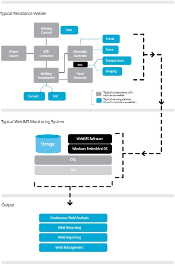
Both the Universal and Custom monitoring systems consist of the following components:
- WeldMS hardware
- WeldMS software
- Sensing devices
Depending on the type of welding machine used and the level of retrofit the machine requires, we assemble the appropriate components.
WeldMS Hardware
An enclosed industrial WeldMS data acquisition box with an IP rating suited for the environment is responsible for receiving and processing signals from each sensing device. Each box contains:
- an extreme temperature range (-40C to 85C), single-board computer
- a high bandwidth, high precision i/o board
- signal conditioners
- a large storage medium
All components are solid-state and built to endure harsh environments. The WeldMS signal box will interface with up to fourteen relay signals and sixteen sensing devices. The box extracts data in real-time with a resolution of 20-bit and a sampling rate of up to 1MHz. The design supports all outputs generated by a variety of sensing devices and produces a very high sample rate -- required for an extensive and effective weld analysis.
Sensing Devices
The sensing devices measure key welding variables. Depending on the type of resistance welder, a minimum set of sensing devices is required to properly monitor and analyze a weld. Most welders are already equipped with sensing devices required by it's controller. WeldMS can also supply any required sensing devices for welders that are not adequately equipped.
Common sensing devices and metrics are listed in the table below:
| Metric | Sensor | Units |
|---|---|---|
| Time | System clock on the single board computer | Second, cycle |
| Electric Welding Voltage | Voltmeter sensor to measure the welder’s transformer secondary voltage | Volt in true RMS |
| Electric Welding Current | A hall-effect sensor or Rogowski coil to measure the welder’s transformer secondary current | Amperes in true RMS |
| Displacement | A potentiometer or encoder to measure the electrode displacement | Inch or millimeter |
| Pressure | Displacement or diaphragm-type pressure sensors to measure the clamping pressure of the electrodes and/or the pressure on the lap or butt joints | Pound-force per square inch or bars or kilopascal |
| Force | Load cell, Piezoelectric, or Capacitive force sensors to measure the clamping force of the electrodes and/or the force on the lap or butt joints | Kilonewtons or Tonne-force |
| Temperature | Thermocouple, resistive-temperature device (RTD), thermistor or pyrometer sensor to measure the heat affected zone of the weld, the electrodes cooling rate, the pre/post annealing temperatures | Fahrenheit or Celsius |
| Thermal image | Photon detector and thermal imaging camera for measuring the temperature distribution at the weld. Also very effective in measuring the welder’s heat distribution during welding for preventive maintenance |
WeldMS Software
WeldMS runs on an embedded Microsoft Windows® platform providing a user-friendly environment without sacrificing performance or stability. The diagram below shows core software components grouped under three main areas: Monitoring, Management and Settings.
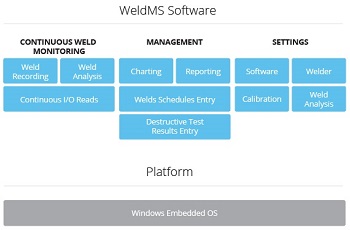
Each component can be modified or new ones added to meet your needs.
 Monitoring
The monitoring component consists of several sub-components working together to collect and interpret the welding signals from the sensing devices. The monitor continuously reads configured welding signals at a predetermined sampling rate up to 1MHz. Each signal is converted into their respective real units and displayed on screen. For each welding cycle, the signals are recorded and analyzed at the end of the cycle against baseline specifications set within the Settings module. The result of the analysis is displayed on screen so that operators can see at a glance whether the weld is flagged for review. This process of monitoring, recording and analyzing occurs continuously for each welding cycle without any operator intervention.
 Management
Multiple software sub-components handle the overall management of all recorded welds. Each archived weld holds all the recorded welding data along with its results. Any welds can be traced using its unique identification number. This allows on-demand viewing of each weld in several chart or report formats depicting the welding data; the result of the weld and its key welding variables that have either met or failed to meet the baseline specifications.
Each archived weld can also be linked with additional information entered by the operator. This may include the welding parameters used by the welder’s controller and the results of any destructive and non-destructive tests. These additional pieces of information not only provide a digital record for future use, but also supply key information for our analytical service.
 Settings
There are several sub-components that deal with the overall settings of the monitoring system. The software settings component handles all settings related to the configuration of the software. The welder component handles specific information about the welder including make and unit information as well as the specifications on the welding transformer. The calibration component converts welding signals to their appropriate engineering units. The weld analysis component configures the baseline specifications used by the analysis engine module.